
Project Features:
- Soil-Bentonite Barrier Wall
- 48,476 Linear Feet (LF). 1,446,362 Vertical Square Feet. Maximum of 60-feet deep
- Target Average Permeability of 1 x 10⁻⁷ cm/s
Background:
The site is located in Hendry County on 10,700 acres of former farmland west of LaBelle, FL. Once construction has been completed, the reservoir will hold 170,000 acre-feet of water. The project will provide storage for local runoff, as well as regulatory releases from Lake Okeechobee. This will reduce lake discharges reaching the estuary, improve the health of the Caloosahatchee Estuary revitalizing fish and oyster habitats by reducing the frequency of undesirable salinity ranges. Releases of water from the reservoir during the dry season will provide essential flows, resulting in improved salinity, survival of young fish, shellfish, and improve ecological health.
Project Objectives:
To construct a soil-bentonite (SB) hydraulic barrier wall around the outer perimeter of the proposed basin within the center of the levee. The initial phase of excavation was to be completed from the existing ground surface and extend 5 feet into the confining clay layer. Phase II was constructed from a prepared embankment fill work platform at elevation 47 and tied 3 feet into the Phase I SB wall. The wall alignment was not continuous, requiring the wall to skip past areas of active canals to be completed at a later date.
Description of Work:
Geo-Solutions completed 31,456 LF of barrier wall, totaling 1,028,062 VSF of soil-bentonite (SB) hydraulic barrier wall in Phase 1, and 17,020 LF totaling 418,300 VSF in Phase 2. Phase I wall installation had depths ranging from 0 feet to 60 feet below ground surface, keying a minimum of 5 feet into the confining clay layer. Phase II installation included depths from 23 to 30 fbgs, keying 3 feet into the Phase I wall.
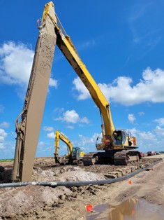
The hydraulic barrier wall was installed using a Komatsu PC 800 excavator and GSI’s long stick and boom configuration with a 36” wide bucket. Bentonite slurry was used to maintain stability during excavation and minimize seepage through the trench sidewalls. The bentonite slurry was mixed onsite in a slurry pond, which was then transferred to a holding pond, then pumped to the trench. Due to the scale of the project, GSI added a second SB wall heading to maintain the project schedule.
Backfill was mixed consisting of trench spoils, bentonite slurry, and dry bentonite addition. To meet site standards, trench spoils that were undesirable for backfill material were removed and clay from an on-site borrow pit were added to the backfill material.
Field observations and testing were conducted during backfill placement to ensure that a consistent adequate mixture was placed. Daily samples were collected and tested per specifications for permeability with a target of 1×10⁻⁷.
Challenges on the site included a segment of Phase 1 wall which contained a layer of cobble and limestone. GSI’s drop chisel was used, in conjunction with a crane to fracture the rock layer to aid in excavation. Additional challenges included the length of the wall. This required GSI to move the slurry ponds and laydown areas eight times throughout the course of the project. Powerlines were a factor in these relocations as well, as the stick had to be removed from the PC800 to advance the machine under these obstacles. Other challenges were weather related, with the project proceeding through four tropical weather events.