
Project Features:
- Soil-Bentonite Hydraulic Barrier Wall
- 3,400 Linear Feet (LF). 61,630 Vertical Square Feet. Maximum of 21-feet deep
- Target Average Permeability of 1 x 10⁻⁷ cm/s
Background:
The site is located in Palm Beach County in close proximity to the Jones/Hungryland Wildlife and Environmental Area and JW Corbett Wildlife Management Area. To the west of the site is an existing wetlands property. According to geotechnical engineering reports the ground water table was encountered at depths of 1-4.5 feet below the existing ground surface. Between ground level and approximately 15 feet below the ground surface soils classify as (SP) Sand and (SC) Clayey Sand. Located below the SP and SC soil layers is a less pervious dense sand with shell fragment stratum.
Project Objectives:
To construct a soil-bentonite (SB) hydraulic barrier wall along the western property boundary to the future warehouse facility between the wetlands and proposed rain water retention basin location. Complete excavation with depths up to 21 feet below the existing ground surface reaching 2.5 feet into the dense sand with shell fragment stratum. Installation of the hydraulic barrier wall with a design that will mitigate potential contamination from intruding on the existing wetlands to the west of the property.
Description of Work:
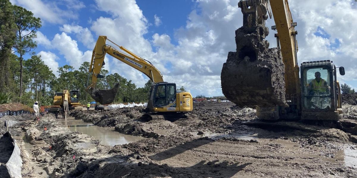
Completed the hydraulic barrier wall is 3,400 LF in length and consists of 61,630 vertical square feet (vsf) of soil-bentonite (SB) hydraulic barrier wall. Wall installation has depths ranging from 13 feet to 21 feet below ground surface, keying a minimum of 2.5 feet into the dense sand with shell fragment stratum excluding sections of the wall which encountered refusal. Refusal was deemed as less than 6 inches of depth excavation in 20 minutes over the length of the current excavation.
The hydraulic barrier wall was installed using a Komatsu PC 490 excavator and GSI’s 24” wide bucket. Bentonite slurry was used to maintain stability during excavation and minimize seepage through the trench sidewalls. The bentonite slurry was mixed onsite in an 18,000 gallon frac tank with mixing paddles and pumped to the trench.
Backfill was mixed consisting of trench spoils, bentonite slurry, and dry bentonite addition. To meet site standards trench spoils that were undesirable for backfill material were removed. For the first 1,400 LF of backfilled trench a dry bentonite addition of 7% was mixed with the trench spoils and bentonite slurry to meet the site specifications. The remaining 2,000 LF was backfilled with a 14% dry bentonite addition as requested by the client.
Field observations and testing were conducted during backfill placement to ensure that a consistent adequate mixture was placed. Daily samples were collected and tested per specifications for permeability with a target of 1×10⁻⁷. Additional backfill samples were collected using GSI’s sampling device at 3 locations (depths of 7’ and 15’) along the trench alignment after backfill placement was completed in the desired sample location areas.
Maintaining the production schedule was a key factor for this project to avoid delaying the remaining site development. While keeping commitment to safety GSI worked through the extreme heat conditions of south Florida and around rain events. GSI kept the project on schedule by safely working through all onsite obstacles and keeping in communication with the client and the site general contractor.